|

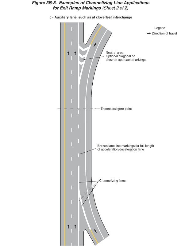
Figure 3B-8. Examples of Channelizing Line Applications for Exit
Ramp Markings (Sheet 2 of 2)
This figure illustrates three examples of channelizing line applications
for exit ramp markings, (a), (b), and (c). The figure is composed
of two sheets.
- Sheet 2 of the figure shows a vertical highway, example (c):
- Example (c), auxiliary lane, such as at cloverleaf interchange,
shows the two right lanes of one direction of a divided highway.
Arrows indicate that the direction of travel is from the bottom
of the figure to the top. A solid yellow line is to the left of
the leftmost through lanes, a solid white line separates the rightmost
travel lane from the right shoulder, and the through lanes are
separated from each other by a broken white line. Near the bottom
of the figure, an entrance ramp from the right side joins the
through roadway. As the entrance ramp approaches the gore, the
solid yellow line to the left of the entering lane changes to
solid white "channelizing lines" that continue past
the gore and join with the wide solid white line from the through
lane to form a triangle. This triangle then changes into a broken
white line that separates the acceleration lane from the through
lanes. A note shows the "broken lane line markings for full
length of acceleration/deceleration lane." The acceleration
lane continues next to the through lanes and then becomes a deceleration
lane as it approaches a right exit ramp. At the "theoretical
gore point," the dotted white line becomes a wide solid white
line that then becomes an elongated white triangle in front of
the gore. A note identifies this as a "neutral area"
with white "optional diagonal or chevron approach markings"
added. The exit ramp curves off to the right.
- A legend shows a black arrow indicating the direction of travel
in the lanes.
Back to: Sheet 1
Back
to Chapter 3B
|

