|

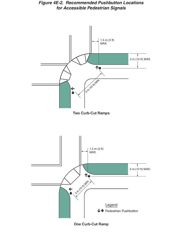
Figure 4E-2. Recommended Pushbutton Locations for Accessible Pedestrian
Signals
This figure contains two examples of the recommended pushbutton
locations for accessible pedestrian signals.
A legend at the bottom of the page shows a black downward-pointing
arrow to the left of a black disc with a short stem on top labeled
"Pedestrian Pushbutton."
The first illustration is entitled "Two Curb-Cut Ramps."
It shows a plan view of one corner of a 90-degree intersection of
two roadways, each with a sidewalk that is separated from the roadway
by a green strip. On the corner radius are shown two curb-cut ramps,
one aligned with the east-west crosswalk and one aligned with the
north-south crosswalk. A left-pointing black arrow is shown above
a black disc with a short stem on top, depicting a pedestrian pushbutton,
is shown just to the right of the green strip near the edge of the
sidewalk, below the east-west crosswalk. To the right of the north-south
crosswalk, just below the green strip near the edge of the sidewalk,
is shown an upward-pointing black arrow to the left of a black disc
with a short stem on the left, depicting a pedestrian pushbutton.
The distance between the two pedestrian pushbuttons is shown as
a diagonal straight-line dimension of 3 m (10 ft) MIN. The distance
from the pedestrian pushbutton to the curb at the edge of the roadway
is shown as a dimension of 3 m (10 ft) MAX. The distance of the
pedestrian pushbutton from the outside edge of the crosswalk is
shown as a dimension of 1.5 m (5 ft) MAX.
The second illustration is entitled "One Curb-Cut Ramp."
It also shows a similar plan view as the first example. The difference
is that only one curb-cut ramp is shown, centered on the corner
radius and leading to both crosswalks. There are also two symbols
for pedestrian pushbuttons shown at the same locations as in the
first example. The dimensioned distances also are the same.
Back
to Chapter 4E
|

